PiggyMeter
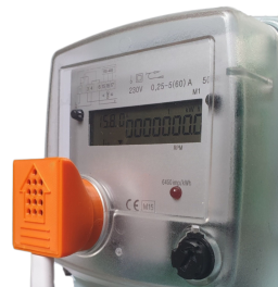
This article shows you how to build a device to remotely read data from an electric meter (or any device with a compatible interface).
It uses widely available components, open source software and is compatible with popular home automation software, Home Assistant.
INFO
A kit for assembling a functional device is available for purchase on Tindie: PiggyMeter KIT.
Features
- Supports IEC62056-21 based protocols
- Supports passive SML protocol using ESPHome native component
- Multiple meters: energy, water, thermal, and more
- Uses open source ESPHome
- Wireless communication via Wi-Fi
- Integrates with Home Assistant
- Optional web server
- Cheap hardware ESP32-C3 or ESP32-S2
- Case design available for 3D print
It supports meters compatible with IEC62056-21 standard that works in modes A, B, C, D (but not E). For details see IEC 62056-21 component.
Note that there are many variations of the protocol. Although the meter may use the same optical interface, the data frame format could be different.
In addition, it supports meters that use SML (Smart Message Language) protocol using ESPHome SML component.
WARNING
DLMS, M-Bus and ANSI C12.18/19 standards are not supported by the software.
How to check if the meter is supported?
IEC 62056-21 term is used for multiple protocols (with the same hardware layer but different data encoding). The device supports meters that provide ASCII-encoded data, something like this:
console
1-0:15.8.1(00000009999.567*kWh)
1-0:15.8.2(00000000000.000*kWh)
1-0:15.8.3(00000000000.000*kWh)
1-0:15.8.4(00000000000.000*kWh)
The meter must be compatible with International Standard IEC 62056-21:2002.
For SML protocol, look for SML logo on the meter or check the manual. ESPHome component only supports passive mode, it does not send any requests to the meter. In that mode, the meter sends data every few seconds.
Meters reported to work with PiggyMeter
The list is created based on user's reports. No guarantee it is accurate.
- Apator Norax 3
- Apator Norax 1
- Apator Norax 1D via SML component
- Pafal 12EA5
- Pafal 4EC9
- Iskra MT372
- Iskra ME162
- Iskra MT851
- Iskra MT831
- Kastrup 382
- Landis+Gyr E350 ZMF110
- ZPA ZE110.D0
- ZPA ZE310
- Daisy Technology ADX10
- SANXING SX330-D5B32-RIFOMN
INFO
Feel free to send an email to info@aquaticus.info if you know the meter that works with PiggyMeter but is not listed above.
Alternative software
PiggyMeter hardware can work with many different meters that utilize optical interface. However, the software currently supports only one standard, practicality limiting the range of supported meters.
You can try to use alternative software that may add support to different meters. It's important to note that there's no assurance it will function seamlessly with PiggyMeter. For support, please reach out to the original author.
- DLMS/COSEM Esphome module https://github.com/viric/esphome-ziv
Bill of materials
| Part | Description |
|---|---|
| CPU | Wemos C3 or S2 Mini https://www.wemos.cc/en/latest/ |
| Optical interface | PiggyMeter PCB https://www.tindie.com/products/32082/ |
| 2×pin header 1×4 | 2.54mm raster; plastic part must be 8.5 mm height |
| Ring Magnet | ⌀30/⌀15×2mm |
| Case | 3D printed case https://github.com/aquaticus/piggymeter_case |
| Washer | 3D printed washer https://github.com/aquaticus/piggymeter_case |
| Lid | 3D printed back lid https://github.com/aquaticus/piggymeter_case |
CPU board
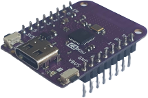
You need a board with Espressif chip installed and compatible Wemos/Lolin pinout. The key factor is location of 4 pins: GND, VCC, TX, and RX.
The size of the PCB is also critical. 3D printed case matches only boards (or their clones) listed below:
- Lolin/Wemos S2 mini
- Lolin/Wemos C3 mini
In theory, you can use any other CPU board with compatible pinout, notable ESP32 and ESP8266 D1 mini. But in that case you must design your own case and modify a bit configuration files (board type and serial port pins).
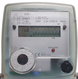
Optical interface
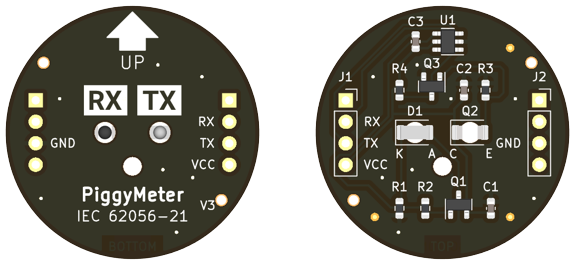
A meter employs an optical interface compatible with IEC62056-21 standard, communicating with a probe via an infrared diode and a phototransistor.
The interface is connected to one of the serial ports on CPU board. Of course you need VCC and GND too.
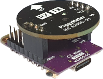
Solder 2 pin headers. You must use pin header 8.5 mm height. The design of the case accommodates this height, ensuring a proper fit. If the height exceeds this dimension, closing the lid may pose challenges.
INFO
You can buy assembled interface on Tindie. 
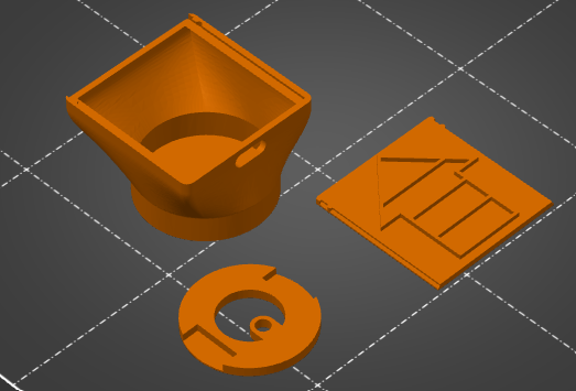
Case
Download files for 3D printer from https://github.com/aquaticus/piggymeter_case. Use V5 version for the latest design.
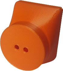
The casing comprises three components:
- the main case,
- a washer,
- and a lid.
There are three distinct STL files available for each component, or alternatively, a single 3fm file incorporating all three elements.
The housing meets the requirements of the IEC62056-21 standard Optical Probe>.
INFO
The housing has a small latch. To close or open it, you need to use some force.
Recommended 3D print settings
- Material: PLA
- Layer: 0.2 mm
- No support
Assembly
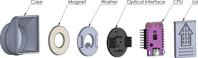
Arrange the components within the case in this order:
- Magnet
- Washer
- Optical interface
- CPU board
- Lid
INFO
Watch assembly on Youtube https://youtu.be/fM2LyJJWQHA?si=dyY4r7zMSMfbwQtm
Programming for IEC62056-21 meters
Begin by installing ESPHome.
Based on your CPU board, select the appropriate configuration file. Additionally, make manual adjustments to certain parameters, such as the WiFi password.
Get configuration files
Clone git repository with configuration files:
bash
git clone https://github.com/aquaticus/piggymeter_esphome_yamlCreate secrets.yaml file
Create a secrets.yaml file within the directory where the configuration files are located. This file will hold the WiFi network name and its corresponding password.
yaml
# Home Assistant API encryption key
api_key: my_home_assistant_encryption_key

# OTA password
ota_pass: my_ota_password

# WiFi network name
wifi_ssid: my_network

# WiFi network password
wifi_pass: my_password
Modify project configuration
The configuration comes pre-set with standard data points for an electric meter.
Feel free to adjust the list, especially if your meter differs from the electric meter type. Refer to the IEC 62056-21 component for further information.
yaml
sensor:
   - platform: iec62056
       obis: 1-0:15.8.0
       name: Absolute active energy total
       unit_of_measurement: kWh
       accuracy_decimals: 3
       device_class: energy
       state_class: total_increasing
Build and flash the firmware
bash
esphome run piggymeter-s2-iec62056-21.yamlThe command above flashes the firmware and show monitor output. By default, the interface reads data from a meter every 1 minute.
TIP
For ESP32-S2 board you must press BOOT button and than RESET button on PCB to enter programming mode. In addition, you can see an error message after flashing -- just ignore it.
log
[12:21:27][D][iec62056.component:232]: Connection start
[12:21:27][D][binary_sensor:036]: 'Meter Connection Status': Sending state ON
[12:21:28][D][switch:013]: 'Internal LED' Turning ON.
[12:21:28][D][switch:056]: 'Internal LED': Sending state ON
[12:21:28][D][iec62056.component:174]: Meter identification: '/XXX6\2YYYYY'
[12:21:28][D][iec62056.component:407]: Meter reported protocol: C
[12:21:28][D][iec62056.component:410]: Meter reported max baud rate: 19200 bps ('6')
[12:21:28][D][iec62056.component:438]: Using negotiated baud rate 9600 bps.
[12:21:29][D][iec62056.component:470]: Switching to new baud rate 9600 bps ('5')
[12:21:29][D][iec62056.component:482]: Meter started readout transmission
[12:21:29][D][iec62056.component:524]: Data: 0-0:C.1.0(12345678)
[12:21:29][D][iec62056.component:524]: Data: 0-0:1.0.0(2000-01-01 20:10:30)
[12:21:29][D][iec62056.component:524]: Data: 1-0:15.8.0(00000001000.657*kWh)
[12:21:29][D][iec62056.component:620]: Set sensor 'Absolute active energy total' for OBIS '1-0:15.8.0'. Value: 1000.656982
[12:21:29][D][iec62056.component:524]: Data: 1-0:15.8.1(00000002000.657*kWh)
[12:21:29][D][iec62056.component:524]: Data: 1-0:15.8.2(00000003000.000*kWh)
[12:21:29][D][iec62056.component:524]: Data: 1-0:15.8.3(00000004000.000*kWh)
[12:21:29][D][iec62056.component:524]: Data: 1-0:15.8.4(00000005000.000*kWh)
[12:21:29][D][iec62056.component:524]: Data: 1-0:15.6.0(00000006000.385*kW)(2000-01-01 20:10:01)
Programming for SML meters
The first steps are identical to those for IEC62056-21 meters.
After cloning the repository and creating the secrets.yaml file, use configuration files for SML meters.
bash
esphome run piggymeter-s2-sml.yamlMost likely, you will need to adjust the configuration file to match the data points transmitted by the meter. It is also worth to verify the baud rate and data bits of the serial port.
Home Assistant
The device should be automatically detected by Home Assistant. If not, you can add it manually by clicking Add Integration and selecting ESPHome integration.
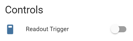
PiggyMeter exposes three group of items:
Readout Trigger
This trigger force PiggyMeter to read data from a meter out of the schedule.
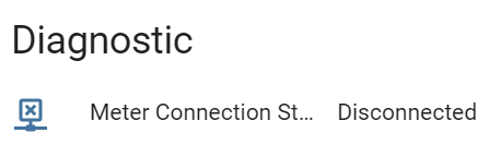
Meter Connection Status
Connected status indicates the interface is exchanging data with the meter.
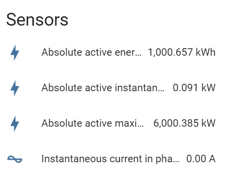
Sensors
This is a list of sensors defined in configuration file.
Standalone mode
PiggyMeter can operate independently of Home Assistant, offering the capability to activate a web server. This server displays data readouts directly in a web browser and offers a simple REST API.
To activate the web server, include the following lines in the configuration file:
yaml
web_server:
  port: 80
More information about web server can be found in ESPHome documentation.
Modifications
By default, the device fetches data every minute, and the internal LED is illuminated during transmission.
Only limited number of OBIS codes are defined in configuration yaml file. It is highly recommended to modify the list of sensors to mach a meter.
Although OBIS codes are standardized, meters may transmit varying numbers of codes. To ascertain the supported codes for your meter, enable DEBUG logging for the IEC62056-21 component component and analyze the log output.
Diagnostic and Problems IEC62056-21
This section is only for IEC62056-21 meters (not SML).
After flashing the firmware, the device will attempt to read data from a meter after approximately 15 seconds. If the transmission fails, it will retry twice every 15 seconds.
You can adjust these parameters by configuring the appropriate tokens. Consult IEC62056-21 component documentation for more details.
It's advisable to switch the default log level from DEBUG to INFO once the device has been confirmed to work correctly.
Below are common issues and their respective solutions.
TIP
Ensure the probe is securely attached to the meter, aligning the arrow on the probe in an upward direction.
No transmission from meter
log
[E][iec62056.component:268]: No transmission from meter.This may indicate:
- Most commonly, the interface is not attached to a meter.
- The interface isn't properly aligned with the optical interface of a meter.
- The meter is not compatible.
Make sure that the optical interface is positioned parallel to the front surface of the housing. If the device works when attached to the meter without the housing, but doesn't work after being inserted into the housing, this could be the issue. In such a case, you may also consider enlarging the two holes in the housing.
Not all sensors received data
log
[E][iec62056.component:644]: Not all sensors received data from the meter. The first one: OBIS '1-0:72.7.0'. Verify sensor is defined with valid OBIS code.This may indicate two problems:
- The meter does not support OBIS code you configured in yaml file. Simply remove sensor with specific OBIS code from configuration.
- There might be a typo or incorrect definition of the OBIS code for the sensor in the configuration file. Double-check the code.
The meter transmits data automatically but the device receives nothing
This indicates the meter supports mode D of IEC62056-21. In this mode, the meter autonomously transmits data every few seconds without requiring a specific request. Ensure that the serial port is configured to align with the meter's transmission format, typically set at 9600 7E1 or 2400 7E1 in most instances.
yaml
# 9600bps for mode D
uart:
    rx_pin: GPIO21
    tx_pin: GPIO22
    baud_rate: 9600
    data_bits: 7
    parity: EVEN
    stop_bits: 1
In addition, Mode D must be manually activated by setting mode_d=True in the platform configuration.
yaml
# Enable mode D
iec62056:
  mode_d: True
Checksum errors
log
[E][iec62056.component:504]: BCC verification failed. Expected 0x6b, got 0x14This error suggests transmission issues.
Usually, the transmission speed is excessively high. Lowering the maximum baud rate should help.
yaml
iec62056:
  baud_rate_max : 4800
Received meter identification but to transmission
log
[D][iec62056.component:174]: Meter identification: '/XXX6\2YYYYYYY'
[D][iec62056.component:252]: The meter is indicating mode E, which is unsupported. Attempting mode C. This will work for meters supporting both mode E and C.
[E][iec62056.component:268]: No transmission from meter.
The meter identification string is successfully received, but there is no data transmission. Additionally, the log displays a message stating, "The meter is indicating mode E."
The meter operates exclusively in mode E, which PiggyMeter does not support. Consequently, the software attempts to switch the meter to mode C, but this attempt fails.
If a meter supports both mode E and C, the system should function correctly.