ESPHome IEC 62056-21 Component
IEC 62056-21 is an international standard for a protocol to exchange data with utility meters. Mostly for electricity but also water, thermal and other meters. It was previously known as IEC 61107.
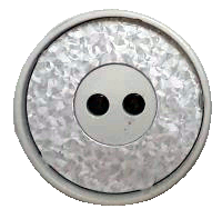
The iec62056 component allows you to read data from any compatible meter. It requires a serial port and an external optical interface. Data exchange uses an infrared optical channel. Compatible meters are equipped with a characteristic round metal plate with two opto-elements inside. The protocol could be used with other transport layers, e.g. current loop but the component was tested only with the optical interface.
It supports 4 modes of IEC 62056-21: A, B, C, and D. Mode E is not supported.
The component does not support programming. Setting meter configuration parameters requires a secret password which makes it impossible to use by ordinary users.
There are other smart meter standards that use the same optical interface. Although they share some common concepts they are not compatible.
Installation
Add the following code to ESPHome YAML configuration file to reference external component.
yaml
external_components:
    # IEC62056 component
    - source: github://aquaticus/esphome-iec62056
Theory of operation
The component operates in 2 main modes:
- Bidirectional communication with a meter. In this mode, a meter sends data only when requested. It requires an IR receiver and transmitter. This is mode A, B and C according to IEC 62056-21.
- Unidirectional communication, where a meter sends data to a probe from time to time. It requires only an IR receiver. In IEC 62056-21 terminology it is mode D.
Modes A, B, C
The component reads data for the first time 15 seconds after boot-up. First, it sends an identification request at 300 bps. The meter returns the maximum baud rate it can handle. Following that, the serial port baud rate is changed to the value provided by the meter or configured by option baud_rate_max. The meter transmits data registers with associated OBIS codes.
If the transmission has failed (bad checksum or invalid format), the component will try to read data again but this time using a slower transmission speed. For every retry, the speed is decreased. The number of retires and delays can be configured.
If the meter is battery-powered, a special wake-up sequence can be applied. This happens only when battery_meter is set to True.
Mode D
For meters operating in mode D, you only need an IR receiver as transmission to a meter is not supported. In this mode, the meter sends data every few seconds without any request. You should configure the serial port to match the meter transmission format. Unlike modes A, B, and C which is detected automatically, Mode D must be enabled manually by setting mode_d=True in the platform configuration.
Mode E
This mode is not supported. Mode E uses binary encoding over HDLC link.
The component try to use mode C for meters reporting mode E. This should work if meter supports both E and C modes. For meters supporting only mode E readout is not possible.
OBIS codes
The OBIS (Object Identification System) code identifies the different readings from a meter. The code consists of up to 6 group sub-identifiers. The code is formatted like this: A-B:C.D.E*F, where:
A- medium: 0=abstract objects, 1=electricity, 6=heat, 7=gas, 8=waterB- channel, 0=no channel availableC- physical value, for example current, voltage, temperature.D- measurement type,E- tariff, 0=total, 1=tariff #1, 2=tariff #2 and so onF- billing period
A, B, and F may be omitted. Codes may use hexadecimal digits, for example, code 15.8.0 could be represented as F.8.0.
The codes are standardized but devices send a different number of codes. To get a list of codes supported by your meter enable DEBUG log for iec62056 component and observe the log output. Sample output:
log
[10:50:12][D][iec62056.component:416]: Data: '1-0:15.8.1(00000009999.567*kWh)'
[10:50:12][D][iec62056.component:416]: Data: '1-0:15.8.2(00000000000.000*kWh)'
[10:50:12][D][iec62056.component:416]: Data: '1-0:15.8.3(00000000000.000*kWh)'
[10:50:12][D][iec62056.component:416]: Data: '1-0:15.8.4(00000000000.000*kWh)'
TIP
Sensor OBIS code must match exactly what is transmitted from a meter. This is the part before the first bracket (.
If an OBIS code is only two digits, you should use quotes in configuration file; for example, "1.2" instead of just 1.2.
For a list of OBIS codes for electric meters, you can visit:
- https://www.promotic.eu/en/pmdoc/Subsystems/Comm/PmDrivers/IEC62056_OBIS.htm
- https://onemeter.com/docs/device/obis/#index
Hardware
To communicate with a meter you must attach an optical interface to the serial port. The interface consists of an infrared LED and phototransistor. In addition, the device must be equipped with a ring magnet to keep it aligned with the meter.
If the meter operates in unidirectional mode D, only an IR phototransistor is required.
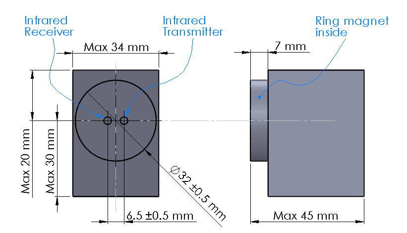
Probe
The standard defines the maximum dimensions of the probe that can be attached to a meter. It must be equipped with a magnet as it is the only way to keep the probe in a stable position.
Configuration
To see meter data in Home Assistant you must define a sensor or text sensor with the appropriate OBIS code. Note that meters support different sets of OBIS codes. By default, the component does not define any sensors.
Serial port
The component requires UART bus. The serial must be configured as 7E1 in most cases. When mode_d=True baud rate must be set to a value supported by the meter. Usually 2400 or 9600 bps. For other modes (mode_d=False) the transmission speed is negotiated with a meter. baud_rate is ignored and can be any value.
yaml
# Example UART configuration entry
uart:
    rx_pin: GPIO21
    tx_pin: GPIO22
    baud_rate: 9600
    data_bits: 7
    parity: EVEN
    stop_bits: 1
WARNING
For ESP8266 it is highly recommended to use hardware UART. Software UART cannot handle transmissions faster than 4800 bps.
You may need to disable logging if the optical probe is connected to the serial port used by the logger component.
yaml
# Set baud_rate to 0 to disable logging via UART.
logger:
    baud_rate: 0
Platform
To use the component you must define iec62056 platform section in the configuration file. It consists of basic settings.
yaml
# Example platform configuration entry for bidirectional communication
iec62056:
  update_interval: 60s
  baud_rate_max: 9600
  battery_meter: False
yaml
# Example platform configuration entry for unidirectional communication
iec62056:
  mode_d: True
Configuration variables
- update_interval (Optional, Time): The interval to read data from a meter. Defaults to
15min.neverdisables updates. In that case, a switch should be used to trigger readout. To get continuous readings use a small value like 1s. - baud_rate_max (Optional, int): Limits the maximum transmission speed to the specified value. By default, it is set to
9600as it provides a stable connection. To disable it, set it to0. That way you can use the maximum possible baud rate of19200if the meter supports it. For ESP8266 use the software UART set to4800or lower. - receive_timeout (Optional, Time): Maximum time component waits for data from a meter before reporting transmission error. Defaults to
3s. - battery_meter (Optional, boolean): Set to true if a meter is battery-powered. That way special power-up sequence will be used.
- retry_delay (Optional, Time): In case of transmission failure, time to wait before retrying transmission. Defaults to
15s. - retry_counter_max (Optional, int): In case of transmission failure, the maximum number of retries. Defaults to
2. - uart_id (Optional, ID: Manually specify the ID of the UART Component if you want to use multiple UART buses.
- mode_d (Optional, boolean): Set to
Trueif a meter sends data every few seconds. This forces the component to operate in mode D. In this mode data is never transmitted to a meter. If set, any other settings exceptreceive_timeoutare ignored. Don't forget to set UART baud rate the meter is using. If you are not sure try2400 7E1or9600 7E1. - on_wait_next_readout (Optional, Automation): An automation to perform when waiting for the next readout.
- on_timeout (Optional, Automation): An automation to perform on read timeout.
- uh50_wakeup (Optional, boolean, default: false): Enables a specialized wakeup sequence for Landis+Gyr UH50 meters. Sends 40 NULL bytes at 300 baud followed by the proprietary service command
/#!\r\n. This wakes the sleeping battery meter and requests the diagnostic/service telegram, which provides live flow rates, temperatures, and current power.
WARNING
Battery-powered meters typically limit the number of readings to preserve energy, e.g. to 4 readings a day. If a meter does not impose the limit, frequent readings may significantly decrease battery life.
Sensor
The sensor reports the first value between brackets from the record. For the following data
log
1-0:15.6.0(00000006000.385*kW)(2000-01-01 20:10:30)the sensor value is 6000.385. To get the second value (date/time in this example) use a Text Sensor.
The sensor supports only decimal values. If the record contains data in any other format you have to use Text Sensor and optionally lambda to convert it to a number.
INFO
The component accepts numbers formatted with either a comma or a dot as the decimal separator. Both 6000.385 and 6000,385 are accepted.
yaml
# Example sensor configuration entries
sensor:
  - platform: iec62056
    obis: 1-0:15.8.0
    name: Absolute active energy total
    unit_of_measurement: kWh
    accuracy_decimals: 3
    device_class: energy
    state_class: total_increasing

  - platform: iec62056
    name: Instantaneous current in phase L1
    obis: 1-0:31.7.0
    unit_of_measurement: A
    accuracy_decimals: 2
    device_class: current
    state_class: measurement

  - platform: iec62056
    name: Instantaneous voltage in phase L1
    obis: 1-0:32.7.0
    unit_of_measurement: V
    accuracy_decimals: 1
    device_class: voltage
    state_class: measurement

  - platform: iec62056
    name: Absolute active instantaneous power
    obis: 1-0:15.7.0
    unit_of_measurement: kW
    accuracy_decimals: 3
    device_class: energy
    state_class: measurement
Configuration variables
- obis (Required): OBIS code.
- index (Optional, int, default: 0): Specifies which value to extract from a multi-value register (e.g. index: 0 for flow temperature and index: 1 for return temperature on OBIS 9.4).
- All other options from Sensor.
Text Sensor
The text sensor provides readout data as a text. In contrast to Sensor, you can select which part of the readout is reported and even send the entire data record back to Home Assistant.
yaml
# Sample text sensor configuration
# Data record:
# 1-0:15.6.0(00000006000.385*kW)(2000-01-01 20:10:30)

text_sensor:
  - platform: iec62056
    obis: 1-0:15.6.0
    group: 2 # "2000-01-01 20:10:30"
    name: Date time

  - platform: iec62056
    obis: 1-0:15.6.0
    group: 1 # "00000006000.385"
    name: Value

  - platform: iec62056
    obis: 1-0:15.6.0
    group: 0 # "1-0:15.6.0(00000006000.385*kW)(2000-01-01 20:10:30)"
    name: The entire record
Configuration variables
- obis (Required): OBIS code. You may define multiple text sensors with the same OBIS but a different group.
- group (Optional, int): Value group,
0,1, or2. Defaults to1. If set to0, the entire data record is reported including OBIS code.1reports the first value,2the second one. - All other options are from Text Sensor.
Data conversion
If a meter reports data as a non-decimal value you can convert it automatically using a template sensor and lambda. Let's assume the meter sends a record like the following one with hex-encoded data:
text
0-0:96.8.0*255(ABCDEF00)First, create a template sensor that will publish data as a decimal value.
yaml
sensor:
  - platform: template
    id: hex_to_dec_sensor
    name: "Converted hexadecimal number"
Now create a text sensor that will receive data as a string, convert it to decimal and publish.
yaml
text_sensor:
  - platform: iec62056
    id: hex_sensor
    obis: 0-0:96.8.0*255
    name: Hex content
    internal: True
    on_value:
      lambda: |-
        std::string hex_str = id(hex_sensor).state;
        uint32_t dec=std::stoul(hex_str, nullptr, 16);
        ESP_LOGI("iec62056.component", "Converted HEX '%s' to %u decimal", hex_str.c_str(), dec);
        id(hex_to_dec_sensor).publish_state((float)dec);
Every time the text sensor receives a new value, it converts it to a decimal and publishes it using the sensor with id hex_to_dec_sensor. The internal flag prevents the sensor to be visible in Home Assistant. In the log you should see:
log
[I][iec62056.component:127]: Converted HEX 'ABCDEF00' to 2882400000 decimalThe same results can be obtained using Home Assistant lambdas. In this scenario, text sensor publishes hexadecimal value and Home Assistant template sensor makes conversion.
Switch
The switch provides the ability to trigger readout on request. When the state is changed from OFF to ON the component initiates data transmission from a meter. You can use the switch in automation.
Configuration variables from Switch can be used.
yaml
# Sample switch configuration
switch:
  - platform: iec62056
    name: 'Readout Trigger'
You cannot trigger readout in mode D.
Binary sensor
Set to ON when transmission to a meter begins. OFF when the transmission is finished.
You can use all configuration variables from Binary Sensor.
yaml
# Sample automation to turn LED on when data read from a meter
switch:
  - platform: gpio
    pin: GPIO2
    name: Internal LED
    id: led_switch
    internal: True

binary_sensor:
  - platform: iec62056
    id: meter_status
    name: Meter Connection Status
    on_press:
      then:
        - switch.turn_on: led_switch
    on_release:
      then:
        - switch.turn_off: led_switch
Collecting workspace information@workspace accuracy and speed can be improved by building a remote workspace index. Learn More
Build remote workspace index
Multiple Meters
The iec62056 component supports managing multiple meters connected to a single ESP32 board. Each meter requires its own UART interface, which can use various meter interfaces such as optical or current loop. Depending on the ESP chip used, you can connect 2-3 meters.
Keep in mind that one UART interface is typically reserved for ESPHome logs. To use it for meters, logging must be disabled.
yaml
# Set baud_rate to 0 to disable logging via UART.
logger:
    baud_rate: 0
Configuration for Multiple Meters
To configure multiple meters, define a dictionary with settings for each meter. Each instance must have a unique id. Additionally, create as many UART components as there are iec62056 components.
Sensors such as binary_sensor, text_sensor, and switch that use the iec62056 platform must include the iec62056_id to reference the specific iec62056 component. Each meter can have its own unique sensor list.
Ensure that sensor name values are unique to clearly identify the data being read from each meter.
INFO
If you encounter the compilation error: Too many candidates found for 'iec62056_id' type 'iec62056::IEC62056Component', ensure that the iec62056_id is correctly added to the sensor configuration.
Example Configuration for 2 Meters
yaml
# define 2 uarts
uart:
  - id: uart_meter1
    rx_pin: 11
    tx_pin: 12
    baud_rate: 300
    data_bits: 7
    parity: EVEN
    stop_bits: 1

  - id: uart_meter2
    rx_pin: 7
    tx_pin: 9
    baud_rate: 300
    data_bits: 7
    parity: EVEN
    stop_bits: 1

# define 2 iec62056 components
iec62056:
  - id: meter1
    uart_id: uart_meter1
    update_interval: 60s
    baud_rate_max: 9600

  - id: meter2
    uart_id: uart_meter2
    update_interval: 70s
    baud_rate_max: 9600

# sample sensors, note iec62056_id
sensor:
  - platform: iec62056
    obis: 1-0:15.8.0
    name: Absolute active energy total meter 1
    unit_of_measurement: kWh
    accuracy_decimals: 3
    device_class: energy
    state_class: total_increasing
    iec62056_id: meter1

  - platform: iec62056
    obis: 1-0:15.8.0
    name: Absolute active energy total meter 2
    unit_of_measurement: kWh
    accuracy_decimals: 3
    device_class: energy
    state_class: total_increasing
    iec62056_id: meter2


switch:
  - platform: iec62056
    name: 'Readout Trigger Meter 1'
    id: 'readout_trigger'
    iec62056_id: meter1

  - platform: iec62056
    name: 'Readout Trigger Meter 2'
    id: 'readout_trigger'
    iec62056_id: meter2
Automations
The iec62056 component supports two automation triggers:
on_timeout: Triggered when a read timeout occurs.on_wait_next_readout: Triggered while waiting for the next readout.
Example Automation Configuration
yaml
iec62056:
  - id: meter1
    uart_id: uart_meter1
    update_interval: 60s
    baud_rate_max: 9600

    on_wait_next_readout:
      - lambda: ESP_LOGI("iec62056.component", "Waiting for the next readout...");

    on_timeout:
      - lambda: ESP_LOGI("iec62056.component", "Read timeout occurred");
      - switch.turn_on: led_switch
      - delay: 1s
      - switch.turn_off: led_switch
Troubleshooting
- Make sure the probe is properly aligned with the optical elements on the meter.
- Meters are usually installed in not very clean areas. You may need to remove dust from the optical interface from time to time.
- If you encounter transmission and BCC checksum errors decrease the baud rate using
baud_rate_maxsetting. - If your device handles multiple sensors that spend a lot of time in the update loop you may need to increase the serial port buffer size. Especially if you note transmission problems when additional sensors are enabled but not when they are disabled.